How access any IoT device or web server behind a Teltonika Networks router

02.06.2021
guide-image

Cellular connectivity is the most favorable way of connecting IoT devices. However, other use cases may encompass many local devices that do not need a SIM card but communicate with a gateway/router. The IoT router is therefore equipped with an emnify SIM and sends the aggregated data through a cellular network to the desired cloud service. Common examples are utility sensors in a building communicating with a smart meter gateway or web servers running in a local network behind a router. Having one device communicating with a platform via cellular connectivity increases efficiency and reduces complexity. But what if you wanted to remotely access a specific device behind the router, for troubleshooting or configuration purposes?

In this blog post I will take you through the necessary steps to remotely access a device behind a router using the remote management system of Teltonika, a raspberry pi hosting a web server behind the router, and a Teltonika router connected with an emnify SIM card.

Diagram showing remote access to an IoT device or web server behind a Teltonika router using Teltonika RMS.

What do I need?

  • Router (I used the Teltonika RUT240)
  • Raspberry Pi (Model 3) hosting a web server or any other device you want to access behind the router
  • emnify IoT SIM

Preparation:

If you have not ordered or registered an emnify SIM yet, you can do so by signing up on the emnify portal. You will get an trial pack including a 10€ free prepaid IoT SIM. Follow this Quick Start Guide to register your SIM card. Then assign the SIM to an endpoint named after the router, in my case I named it “Teltonika RUT240”. 


4 Steps Navigation

1. Connecting and Setting up the Router

2. Adding the Router to Teltonika RMS

3. Connecting the IoT Device to the Router

4. Adding an Remote HTTP access in RMS 

Connecting the Router to the emnify platform with our IoT multi-SIM

Insert the SIM card into the router and attach the two mobile and one WiFi antennas. Plug it in, and connect it to your computer via the provided ethernet cable. Make sure the ethernet cable is in the LAN port of the router. Type the default IP address printed on the router (192.168.1.1) into your browser to access the router’s configuration settings. You will be prompted to login, using “admin/admin01” as a username/password.

The Setup Wizard will take you through 5 steps, in which you can set up network details. Make sure that in Step 5 - RMS the connection type says enabled.

For a more detailed walkthrough on the router setup, watch this video by Teltonika Networks.

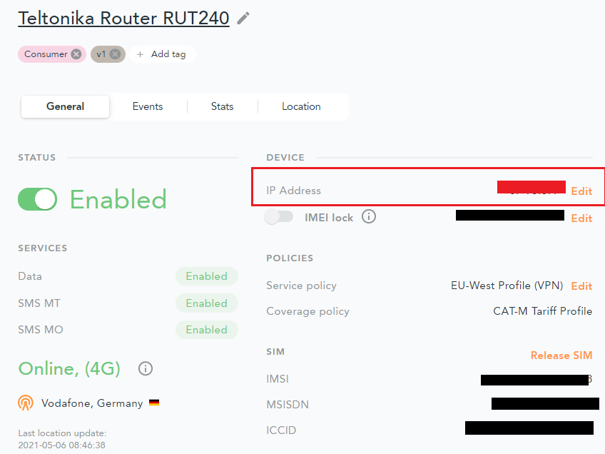
Check the emnify portal to see if the device is online. The IP Address shown below in the red box is the static IP address assigned to your router, which can be used to access and troubleshoot the device itself using emnify’s OpenVPN service.

emnify portal endpoint view highlighting the router’s static IP address (shown in a red box).


Adding the Router to the Remote Management System 

To add your router to the Teltonika RMS service, you need an RMS account. If you have not already set one up, type in rms.Teltonika.lt into your browser and complete the registration.

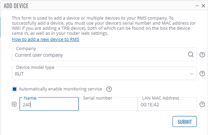
On the left side of RMS portal, click on Devices below Management. Now in the upper row of drop-down menus, hover over Device and click Add Device.

Select your Company and device model type (RUT here), give the device any Name and fill in the Serial Number and LAN MAC Address fields (Both are printed on the device itself).

Click Submit.

Teltonika RMS Add Device form with fields for company, model, name, serial number, and LAN MAC address.

Now you should see an Action Status window, where the system is waiting for the device to connect as shown below:

Teltonika RMS Action Status window showing the system waiting for the device to connect.
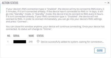
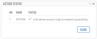
After a short while, the connection will be established and the Action Status window will display the following:

Teltonika RMS Action Status window showing the device connected successfully.
The Device should now be shown on the Management  Devices page in RMS.


Connecting the Raspberry Pi to the Router

Our Raspberry Pi is running a web server for demonstration purposes, which we would like to remotely access using the Teltonika RMS platform. But before we set up the remote access, we must connect the Raspberry Pi to the Teltonika router’s internet via ethernet cable.

First, disconnect the ethernet connection between the Teltonika router and the PC. We need the LAN port of the router to connect to the Raspberry Pi. Then connect the Raspberry Pi to the Teltonika router with the ethernet cable. Now connect your PC to your own WiFi again.

Another great feature of the RMS is that you can access the router's settings / WEB UI through RMS, without being in the same network as the router. We will need to access the router’s settings to check the assigned IP Address of our Raspberry Pi hosting our web server.


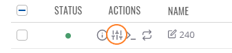
Back on the Management  Devices page in RMS, the previously added router should be listed, with a green status dot indicating a healthy connection. In the Actions column of the device table, there are four icons. Click the circled icon shown below:

Teltonika RMS Devices list showing the Actions column and the circled icon to open remote access to the router UI.

In the Pop-up Window, click Generate to create a time limited access link to your router’s settings. Then click on the link itself. You may need to log into your router again, now with your new password.

Inside the router’s settings, navigate to Status Network LAN

The Raspberry Pi (called catm2 here) should be listed as shown below:

Router LAN status page listing the Raspberry Pi device (catm2) and its assigned IP address.

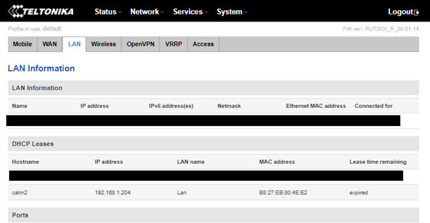
Copy the displayed IP Address of the device and save it temporarily.
Log out of the router’s settings and go back to the RMS portal.

Adding a Remote HTTP access in the RMS portal

We now have all the necessary things to create a remote HTTP access to the web server running on our Raspberry Pi.
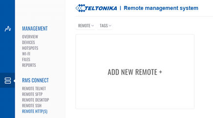
On the left side of the RMS portal, click on Remote HTTP(S) below RMS Connect. Then click Add New Remote+

Teltonika RMS Connect screen showing Remote HTTP(S) and the Add New Remote button.

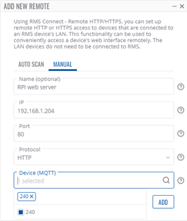
In the pop-up menu, select manual instead of auto-scan. Give your Remote Connection a name, here I used “rPi web server”.
Insert the IP Address of the web server (on our Raspberry Pi) that you noted down earlier. The default port is 80.
Select a protocol type, in this example we use HTTP.
Then select a device registered to your RMS account, so a router which the web server is running on, in our case that is the RUT240 we set up.

Click ADD.

Remote HTTP(S) configuration popup showing manual setup with name, IP address, port 80, protocol HTTP, and selected device.

Click on your newly created Remote. To connect to your web server running behind your Teltonika router, click connect at the top of the pop-up window.

Teltonika RMS Remote HTTP entry opened, showing the Connect button to start the remote session.

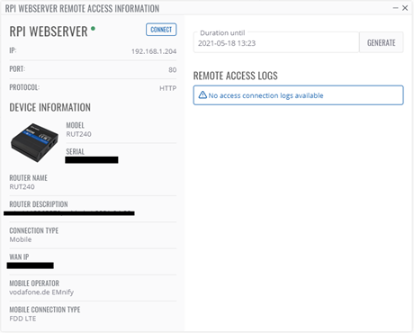
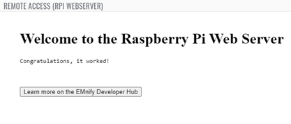
If everything worked, you should see your web server in a new pop-up window, as shown below.

Browser window showing the Raspberry Pi web server successfully accessed through Teltonika RMS remote HTTP connection.

Related Posts

Image for post LwM2M vs MQTT: Which one is the best for IoT Solutions?

LwM2M vs MQTT: Which one is the best for IoT Solutions?

While building IoT solutions, keeping the footprint small is of utmost importance. This requirement influences all design aspects of IoT solutions, including communication. Transferring data from your IoT devices to your application servers efficiently is important, but at the same time, you also need to have a lightweight way of doing so. In this post, I will compare MQTT and LwM2M communication protocols for IoT solutions. What are Communication Protocols? Simply put, communication protocols are rules that define how two connected systems communicate with each other. These protocols cover everything from authentication, signalling, security, data transfer, flow control to error detection and handling. The Internet of Things drives innovation in these protocols to make them more efficient and secure among other things. What is MQTT? MQTT stands for MQ Telemetry Transport where the MQ part comes from an IBM product called the MQ Series. MQTT is a protocol that was specifically built for M2M and IoT message transfer by Andy Stanford-Clark (IBM) and Arlen Nipper (Arcom). The protocol helps transfer messages using the publish and subscribe model which enables it to send messages to one or multiple subscribers. What is LwM2M? LwM2M stands for Light Weight M2M. It is a protocol designed by OMA SpecWork’s for device management but is also suitable for data transfer with the objective of attaining reduced power and data consumption. It is built on top of CoAP (Constrained Application Protocol) which increases its bandwidth efficiency. LwM2M has a transport agnostic design which by default uses UDP, but also supports TCP and SMS. Architecture MQTT As mentioned, MQTT has a publisher and subscriber model. There is no direct connection between the sender of the message and the receiver. There are 2 basic components in this architecture. Client Broker Clients can publish messages on topics to the broker. The broker then dispatches these messages to any clients that subscribe to that topic. Thus the broker decouples the publisher and the subscriber. MQTT brokers do not normally store messages, but do offer buffering of messages in some cases. MQTT uses TCP/IP to connect to the broker. The broker authenticates and authorizes the clients and maintains the session data of all active clients. The broker is responsible for receiving all messages, filtering the messages, determining who is subscribed to each message, and sending the message to these subscribed clients. LwM2M In an attempt to standardize device management and telemetry, LwM2M supports device management functions, in addition to data reporting (as MQTT does). Bootstrapping Device Configuration Firmware Update Fault Management Configuration & Control Reporting For all the above functions there are procedures defined, e.g. how the device registers at the server, or how the server initiates a client diagnosis. The common structure under all the above functions is a client - server model. The client initiates the connection with the server. The server then uses REST APIs to perform either of the above functions. Implementation MQTT An MQTT client can be any device that runs the MQTT library and connects to the MQTT broker and can have a very small footprint depending on the library used. An MQTT client usually sends data to the server, such as telemetry data. It contains scripts to publish messages to a topic. There are several MQTT client libraries available depending on your preferred programming language. An MQTT broker is the heart of this protocol and can handle millions of MQTT clients depending on the implementation. An MQTT broker needs to be highly scalable, integrated into your backend systems, and failure-resistant. The broker needs to receive, filter and forward all messages to the clients that subscribe to them. As mentioned earlier, it needs to maintain the data-sessions of all the clients connected to it. There are several implementations of the MQTT broker available as open-source or paid. LwM2M Depending on the function that you are using it for, there can be several implementations of the LwM2M client and server. The LwM2M client initiates a connection with the server. LwM2M uses a simple resource model with the core set of objects and resources defined in the specification. As an example, the device here is an object, with id 3 and the device has resources like firmware version, serial number, etc. which have a fix resource id. So to get information about a particular resource of the object device, the server can send a call like READ 3/3/0. The LwM2M client implementation contains code to initiate the connection with the server with credentials, sending the necessary data requested by the server, callback functions for LwM2M resource executions and send error events. It can also contain other functions depending on the use-case. The LwM2M server on the other hand needs to authenticate LwM2M clients, send correct requests using the REST API and process the requested information. There are several open-source as well as paid implementations available for the LwM2M client as well as server. LwM2M also has a Developer Toolkit which can be used to implement your own versions. Security MQTT MQTT supports various authentications and data security mechanisms. These mechanisms are configured on the broker and the client needs to comply with these mechanisms. MQTT uses TCP/IP and you can also leverage Transport Layer Security (TLS) to use secure the connection. LwM2M LwM2M also supports authentication and data transport security mechanisms. LwM2M uses CoAP which usually uses UDP as the transport protocol. When using UDP, LwM2M supports DTLS. CoAP also supports TCP and TLS accordingly. Use Cases MQTT MQTT is used for sending payload for low-power and constrained applications, thus making it a favorite choice for many IoT applications. MQTT brokers are a big component of Cloud based IoT solutions. Logistics - for connectivity and real-time monitoring of vehicles Manufacturing - For monitoring of manufacturing plants Smart Home - For energy monitoring, home security, home patient monitoring Oil and Gas - The use-case it was first built for, to monitor the oil pipelines Consumer products - Like smart appliances Urban Mobility - For city transportation systems, car sharing etc. LwM2M While LwM2M also supports sending telemetry data, it was built to standardize device management and provisioning, thus making it ideal for the 6 functions that it defines in its implementation. Bootstrapping - Enables headless device management, thus enabling shipping the devices without configuring them in the factory. Device Configuration - Enables device life cycle functionalities like enable, disable and update. Firmware Update - Enables FOTA/ SOTA for devices. Fault Management - Enables monitoring of statuses like battery level, memory, sw/hw version etc. Configuration & Control - Enables setting of APN and other functionalities for cellular connectivity, as well as activating, rebooting and disabling the device. Reporting - Enables error reporting from the devices Conclusion While deciding the right protocol for sending essential data from your connected devices to your application, the question is not whether you use MQTT or LwM2M. From the above description, you can see that both protocols were designed for different and specific purposes. So if your application needs a higher payload of data to be sent, you might choose MQTT and will have to implement functionalities like device provisioning, OTA on top of it. On the other hand, if the application needs to monitor critical statuses on the device, as well as needs the convenience of lightweight device management, you might want to choose LwM2M. Platforms like AWS IoT, Azure IoT Hub have an inbuilt version of the MQTT broker which you can use to send payload through your device. You then only have to configure the MQTT client on the device. The device management in AWS IoT and Azure IoT hub is then done through device shadow and device twins respectively. If you are hosting and managing your own cloud applications, you can use LwM2M for device management and build your own MQTT broker for messaging. There can also be use-cases where you might need to use a combination of both. In any case, it is important to understand that MQTT and LwM2M protocols are not replacements of one another but built for distinct use-cases. Stay glued to this space to see a comparison between MQTT and CoAP next. And if you wish to know more about protocols and IoT check out our Comprehensive Guide to IoT Protocols. Until then, Stay Connected!