How to fit a Raspberry Pi with mobile connectivity

11.10.2015
guide-image

The Raspberry Pi is a great platform to prototype and realize projects for IoT. Network connectivity can easily be established via its build-in Ethernet interface or an optional Wifi dongle.

Although, when it comes to projects that need mobile connectivity, things can get a little bit more complicated in terms of device configuration, remotely controlling the network access and choosing the right mobile provider to ensure a reliable, secure and cost-efficient setup.

In our blog post we will guide you through the steps to set up, monitor and control mobile M2M connectivity on the Raspberry Pi using a Huawei USB Modem E398 fitted with the EMnify M2M SIM.

Hardware Requirements

  • Raspberry Pi installed with Raspbian OS
  • Huawei LTE USB Modem E173
  • EMnify M2M SIM

Required Debian Packages

  • ppp - Point-to-Point Protocol (PPP) – daemon
  • usb-modeswitch – mode switching tool for controlling “flip flop” USB devices
  • usb-modeswitch-data – mode switching data for USB-modeswitch

You can install these packages via apt-get.  To do so, log in as ‘root’ to the Raspberry Pi and run the following command:
apt-get install ppp usb-modeswitch usb-modeswitch-data

Configure Huawei USB Stick

The Huawei stick can work in two different modes: storage and modem. To work together with the PPP Daemon we need to ensure it is switched to modem mode on startup, the usb-modeswitch tool will do this for you, but first you need to find the vendor and product ID, so that you can add the correct usb-modeswitch configuration.

Plug in the USB and then run lsusb, you should see the following output

root@sn-box:~# lsusb

Bus 003 Device 003: ID 12d1:1436 Huawei Technologies Co., Ltd. Broadband stick

Bus 001 Device 001: ID 1d6b:0002 Linux Foundation 2.0 root hub

Bus 002 Device 001: ID 1d6b:0001 Linux Foundation 1.1 root hub

Bus 003 Device 001: ID 1d6b:0002 Linux Foundation 2.0 root hub

Bus 004 Device 001: ID 1d6b:0001 Linux Foundation 1.1 root hub

Now we need to add the required configuration to /etc/usb_modeswitch.conf

DefaultVendor=0x12d1

DefaultProduct=0x1436

MessageEndpoint="0x01"

MessageContent="55534243123456780000000000000011062000000101000100000000000000"

To check if it is working you need to reboot the Raspberry Pi and - if it has worked correctly - you will find the log messages about the switching in /var/log/syslog

May 11 21:56:36 sn-box usb_modeswitch: switching device 12d1:1446 on 001/007

May 11 21:56:36 sn-box kernel: [ 533.141948] ehci_irq: port change detect

May 11 21:56:36 sn-box kernel: [ 533.145965] usb 1-1: USB disconnect, device number 7

May 11 21:56:39 sn-box kernel: [ 536.982223] ehci_irq: port change detect

May 11 21:56:40 sn-box kernel: [ 537.261862] usb 1-1: new high-speed USB device number 8 using sw-ehci

May 11 21:56:40 sn-box kernel: [ 537.424772] usb 1-1: New USB device found, idVendor=12d1, idProduct=1436

May 11 21:56:40 sn-box kernel: [ 537.444195] usb 1-1: New USB device strings: Mfr=4, Product=3, SerialNumber=0

May 11 21:56:40 sn-box kernel: [ 537.461071] usb 1-1: Product: HUAWEI Mobile

May 11 21:56:40 sn-box kernel: [ 537.475642] usb 1-1: Manufacturer: HUAWEI Technology

May 11 21:56:40 sn-box kernel: [ 537.496180] option 1-1:1.0: GSM modem (1-port) converter detected

May 11 21:56:40 sn-box kernel: [ 537.515557] usb 1-1: GSM modem (1-port) converter now attached to ttyUSB0

May 11 21:56:40 sn-box kernel: [ 537.542851] cdc_ether 1-1:1.1: wwan0: register 'cdc_ether' at usb-sw-ehci-1, Mobile Broadband Network Device, 02:50:f3:00:00:00

May 11 21:56:41 sn-box logger: usb_modeswitch: switched to 12d1:1436 on 001/008

Add ppp interface configuration

In the next step we add a new interface configuration to enable the ppp interface in /etc/network/interfaces

auto gprs

iface gprs inet ppp

provider gprs

and we add a corresponding peer configuration file ‘gprs’ in /etc/ppp/peers

user "emnify"

connect "/usr/sbin/chat -v -f /etc/chatscripts/gprs -T em"

/dev/ttyUSB0

noipdefault

defaultroute

replacedefaultroute

hide-password

noauth

persist

usepeerdns

Start the ppp interface

ifup gprs

Now the pppd will initialize the modem and start the ppp connection, if everything went fine you will see a ppp0 interface with IP address assigned and corresponding entries in the routing table:

root@sn-box:~# ifconfig ppp0

ppp0 Link encap:Point-to-Point Protocol

inet addr:10.199.1.38 P-t-P:10.64.64.64 Mask:255.255.255.255

UP POINTOPOINT RUNNING NOARP MULTICAST MTU:1500 Metric:1

RX packets:499 errors:0 dropped:0 overruns:0 frame:0

TX packets:591 errors:0 dropped:0 overruns:0 carrier:0

collisions:0 txqueuelen:3

RX bytes:66122 (64.5 KiB) TX bytes:99537 (97.2 KiB)
root@sn-box:~# route -n

Kernel IP routing table

Destination Gateway Genmask Flags Metric Ref Use Iface

0.0.0.0 0.0.0.0 0.0.0.0 U 0 0 0 ppp0

10.64.64.64 0.0.0.0 255.255.255.255 UH 0 0 0 ppp0

… let’s check if you’re connected to the internet:

>root@sn-box:~# ping 8.8.8.8

PING 8.8.8.8 (8.8.8.8) 56(84) bytes of data.

64 bytes from 8.8.8.8: icmp_req=1 ttl=55 time=101 ms

64 bytes from 8.8.8.8: icmp_req=2 ttl=55 time=99.5 ms

64 bytes from 8.8.8.8: icmp_req=3 ttl=55 time=98.2 ms

From now on the Raspberry Pi will automatically connect on startup and also retry to connect in case the connection is lost or interrupted.

Monitor M2M connectivity in the EMnify Portal

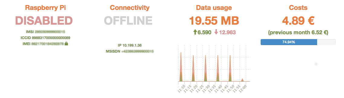
Through fitting our Raspberry Pi with an EMnify M2M SIM we can control and monitor its network connectivity in real-time using the EMnify Portal. It allows us to check the current connectivity status, location and on-going data usage:

[gallery columns="2" size="medium" link="file" ids="24270,24271"]

Control network access remotely

Imagine you have deployed your Raspberry Pi on a remote location and you want to temporary disable network access due to security or cost reasons.

Doing this on application level requires remote access and reactivation at a later stage can be tricky. The EMnify IoT Portal allows you to perform this task with a single mouse click. Use the “Disable” button and your Raspberry Pi will be instantly and securely disconnected from the network.

Screen-Shot-2015-06-18-at-14.06.36

The PPP Daemon on the Raspberry Pi will recognise this nicely and shutdown the connection.

Jun 18 12:17:05 sn-box pppd[14614]: Modem hangup

Jun 18 12:17:05 sn-box pppd[14614]: Connection terminated.

Jun 18 12:17:06 sn-box pppd[14614]: Script /etc/ppp/ip-down finished (pid 15807), status = 0x0

This will also be reflected in real-time on the EMnify IoT Portal

Screen-Shot-2015-06-18-at-14.05.45

Also if you want to enable network access again at a later stage you can use the “Enable” button in the EMnify IoT Portal and your Raspberry Pi will turn back online.

In our blog post you have seen how easy it is to connect and control the M2M network connectivity of a Raspberry Pi when managed through the EMnify IoT Platform.

In our next posts we will elaborate on how to use the advanced features of the EMnify Platform to provision endpoints and SIM cards, to set up usage policies and manage these functions in an automated way through our API.

In the meantime, if you have questions about our services or are looking for reliable and secure mobile connectivity for your M2M/IoT devices, please send us an email via our contact page.


What can your connectivity provider do for your device security? 

Check out our Guide for Cellular IoT Securityfor 25+ best practices
to ensure a secure IoT solutionfor your business.

New call-to-action

Related Posts

Image for post LwM2M vs MQTT: Which one is the best for IoT Solutions?

LwM2M vs MQTT: Which one is the best for IoT Solutions?

While building IoT solutions, keeping the footprint small is of utmost importance. This requirement influences all design aspects of IoT solutions, including communication. Transferring data from your IoT devices to your application servers efficiently is important, but at the same time, you also need to have a lightweight way of doing so. In this post, I will compare MQTT and LwM2M communication protocols for IoT solutions. What are Communication Protocols? Simply put, communication protocols are rules that define how two connected systems communicate with each other. These protocols cover everything from authentication, signalling, security, data transfer, flow control to error detection and handling. The Internet of Things drives innovation in these protocols to make them more efficient and secure among other things. What is MQTT? MQTT stands for MQ Telemetry Transport where the MQ part comes from an IBM product called the MQ Series. MQTT is a protocol that was specifically built for M2M and IoT message transfer by Andy Stanford-Clark (IBM) and Arlen Nipper (Arcom). The protocol helps transfer messages using the publish and subscribe model which enables it to send messages to one or multiple subscribers. What is LwM2M? LwM2M stands for Light Weight M2M. It is a protocol designed by OMA SpecWork’s for device management but is also suitable for data transfer with the objective of attaining reduced power and data consumption. It is built on top of CoAP (Constrained Application Protocol) which increases its bandwidth efficiency. LwM2M has a transport agnostic design which by default uses UDP, but also supports TCP and SMS. Architecture MQTT As mentioned, MQTT has a publisher and subscriber model. There is no direct connection between the sender of the message and the receiver. There are 2 basic components in this architecture. Client Broker Clients can publish messages on topics to the broker. The broker then dispatches these messages to any clients that subscribe to that topic. Thus the broker decouples the publisher and the subscriber. MQTT brokers do not normally store messages, but do offer buffering of messages in some cases. MQTT uses TCP/IP to connect to the broker. The broker authenticates and authorizes the clients and maintains the session data of all active clients. The broker is responsible for receiving all messages, filtering the messages, determining who is subscribed to each message, and sending the message to these subscribed clients. LwM2M In an attempt to standardize device management and telemetry, LwM2M supports device management functions, in addition to data reporting (as MQTT does). Bootstrapping Device Configuration Firmware Update Fault Management Configuration & Control Reporting For all the above functions there are procedures defined, e.g. how the device registers at the server, or how the server initiates a client diagnosis. The common structure under all the above functions is a client - server model. The client initiates the connection with the server. The server then uses REST APIs to perform either of the above functions. Implementation MQTT An MQTT client can be any device that runs the MQTT library and connects to the MQTT broker and can have a very small footprint depending on the library used. An MQTT client usually sends data to the server, such as telemetry data. It contains scripts to publish messages to a topic. There are several MQTT client libraries available depending on your preferred programming language. An MQTT broker is the heart of this protocol and can handle millions of MQTT clients depending on the implementation. An MQTT broker needs to be highly scalable, integrated into your backend systems, and failure-resistant. The broker needs to receive, filter and forward all messages to the clients that subscribe to them. As mentioned earlier, it needs to maintain the data-sessions of all the clients connected to it. There are several implementations of the MQTT broker available as open-source or paid. LwM2M Depending on the function that you are using it for, there can be several implementations of the LwM2M client and server. The LwM2M client initiates a connection with the server. LwM2M uses a simple resource model with the core set of objects and resources defined in the specification. As an example, the device here is an object, with id 3 and the device has resources like firmware version, serial number, etc. which have a fix resource id. So to get information about a particular resource of the object device, the server can send a call like READ 3/3/0. The LwM2M client implementation contains code to initiate the connection with the server with credentials, sending the necessary data requested by the server, callback functions for LwM2M resource executions and send error events. It can also contain other functions depending on the use-case. The LwM2M server on the other hand needs to authenticate LwM2M clients, send correct requests using the REST API and process the requested information. There are several open-source as well as paid implementations available for the LwM2M client as well as server. LwM2M also has a Developer Toolkit which can be used to implement your own versions. Security MQTT MQTT supports various authentications and data security mechanisms. These mechanisms are configured on the broker and the client needs to comply with these mechanisms. MQTT uses TCP/IP and you can also leverage Transport Layer Security (TLS) to use secure the connection. LwM2M LwM2M also supports authentication and data transport security mechanisms. LwM2M uses CoAP which usually uses UDP as the transport protocol. When using UDP, LwM2M supports DTLS. CoAP also supports TCP and TLS accordingly. Use Cases MQTT MQTT is used for sending payload for low-power and constrained applications, thus making it a favorite choice for many IoT applications. MQTT brokers are a big component of Cloud based IoT solutions. Logistics - for connectivity and real-time monitoring of vehicles Manufacturing - For monitoring of manufacturing plants Smart Home - For energy monitoring, home security, home patient monitoring Oil and Gas - The use-case it was first built for, to monitor the oil pipelines Consumer products - Like smart appliances Urban Mobility - For city transportation systems, car sharing etc. LwM2M While LwM2M also supports sending telemetry data, it was built to standardize device management and provisioning, thus making it ideal for the 6 functions that it defines in its implementation. Bootstrapping - Enables headless device management, thus enabling shipping the devices without configuring them in the factory. Device Configuration - Enables device life cycle functionalities like enable, disable and update. Firmware Update - Enables FOTA/ SOTA for devices. Fault Management - Enables monitoring of statuses like battery level, memory, sw/hw version etc. Configuration & Control - Enables setting of APN and other functionalities for cellular connectivity, as well as activating, rebooting and disabling the device. Reporting - Enables error reporting from the devices Conclusion While deciding the right protocol for sending essential data from your connected devices to your application, the question is not whether you use MQTT or LwM2M. From the above description, you can see that both protocols were designed for different and specific purposes. So if your application needs a higher payload of data to be sent, you might choose MQTT and will have to implement functionalities like device provisioning, OTA on top of it. On the other hand, if the application needs to monitor critical statuses on the device, as well as needs the convenience of lightweight device management, you might want to choose LwM2M. Platforms like AWS IoT, Azure IoT Hub have an inbuilt version of the MQTT broker which you can use to send payload through your device. You then only have to configure the MQTT client on the device. The device management in AWS IoT and Azure IoT hub is then done through device shadow and device twins respectively. If you are hosting and managing your own cloud applications, you can use LwM2M for device management and build your own MQTT broker for messaging. There can also be use-cases where you might need to use a combination of both. In any case, it is important to understand that MQTT and LwM2M protocols are not replacements of one another but built for distinct use-cases. Stay glued to this space to see a comparison between MQTT and CoAP next. And if you wish to know more about protocols and IoT check out our Comprehensive Guide to IoT Protocols. Until then, Stay Connected!